Roland G-202 Guitar Synthesizer
Controller
Features and Specifications:
Body: Ash
Finishes available: Acrylic, red, white, blue, natural
Neck: Maple One Piece
Fingerboard: Maple
Frets: 21
Bridge: Adjustable
Nut: Polycarbonate
Tuning machines: Gotoh
Pickups: Two Roland PU-120H humbuckers
Scale:25 1/2"
Truss Rod: Single, Adjustable
Neck Width: 1 5/8"
Body Width: 13"
Body Depth: 1 3/4"
Overall Length: 39 1/2"
Weight: 7 lbs 3 oz
The Roland G-202 guitar is the least known
of all the vintage Roland guitar synthesizer controllers. The unusual G-202
is a bit of a Fender/Gibson hybrid. While the body shape and neck are the
same as the Fender-inspired G-505, the G-202 has a fixed bridge with humbucker
pickups. The knobs are the same ones as used on the G-303/G-808 guitars,
but the Roland PU-120H pickups and TP-130 bridge appear only on the G-202.
For people who like the Fender design, but do not want the issues involved
with a floating, tremolo bridge, the G-202 is their "go to" vintage Roland
guitar synthesizer controller.
The Unique G-202 Electronics Card
Most notably, the G-202 guitar has its own electronic card which is
distinctly different from the cards used in the G-303/G-505/G-808. The
most obvious difference is that the G-202 card has the components (resistors,
capacitors, opamps, etc.) installed on the same side of the board as the
control pots. In the G-303/505/808 cards, the control pots are installed
on one side, and the components on the opposite side.
The G-202 has 1S188 diodes, and uses them not as noise gates, but to
provide the waveform clipping to produce the fuzz sound. The G-202 does
not have the additional opamp stage or any additional capacitors to smooth
out the fuzz tone. As a result the G-202 is not as dense or smooth as the
G-303/505/808. e same size, a G-505 card can be installed in a G-202 guitar
without any changes.
Notes on the G-202
and GR-300 from Manuals and Reviews
In the early '80s, before the MIDI specification was adopted, Roland
offered a series of guitars with built-in hex pickups, for use with their
GR-300
analog synthesizer, which applied analog synthesizer-style sound shaping
to sounds from the hex-fuzz generator built into the guitar. The GR-300
polyphonic guitar synthesizer has an outstanding expressing ability, being
able to reproduce the subtleness of the guitar sound which cannot be obtained
by a keyboard synthesizer. It is especially suitable for live performance.
The guitars designed as controllers for the GR-300 were the G-202,
G-303,
G-505,
and G-808-- included built-in controls for several synthesizer functions,
and used an impressive 24-conductor cable with massive connectors to interface
with the synthesizer or hex fuzz unit.
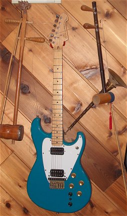
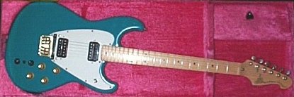
G-202 Guitar Synth Controller (1980 to 1984)
This guitar is a solid-body, offset double cutaway body "Stratocaster-style"
with bolt-on solid maple neck, dual neck/bridge humbucking pickups, built-in
hex pickup, onboard synth controller electronics, controls: guitar volume,
tone, synthesizer VCF cutoff, guitar/synth mix, VCF resonance (feedback)
and LFO depth (synth vibrato). Fully adjustable bridge. The model was available
in bright enamel finishes.
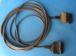
All of the GR System products use the same 24-pin. C-24D connector.
The C-24D uses locking mechanisms at both ends to prevent the cord from
detaching from the Controller and Unit.
GR-300 Guitar Synthesizer
The blue GR300 has six VCOs (one per string) that are controlled by
the string pitches as well as hexa-fuzz plus an LFO, tuning presets and
some control over the attack of each note. The decay of each note is controlled
by the way you play the guitar and this makes the system far more versatile
than it first appears. As one of the sound sources on this unit are now
true VCOs then a few new techniques become available. First it is now possible
to apply vibrato to open strings, secondly each string can now produce
two notes (one from the divided pickup and one from a VCO). The pitch of
the VCO's can be offset by two preset controls that can be selected by
footswitches. Envelope attack can be slowed down and the strings that will
have a synthesized tone on them can be individually selected. There is
a compression on / off switch but unfortunately the infinite sustain of
the GR500 was dropped. Many of these functions can be selected by footswitches
and the state of these are indicated by LEDs that flash if the function
is off or steady if the function is on.
The guitar controllers for the GR300 were the same range that were offered
for use with the GR100. The controls on the guitars now allowed control
of VCF frequency and resonance, guitar / synth balance, oscillator / hexa-fuzz
selection and LFO on / off through the use of two concealed touch plates.
All this was achieved on guitars that looked very conventional, however
examination of the back of the guitar shows that there is a large amount
of electronics inside it.
The improved tracking of the GR-300 combined with the GK1 and BK1 pickups
offered clean and fast tracking which allowed guitarists much more versatility
in their playing. The system is still considered one of the greatest guitar
synths ever manufactured despite the limitations of the synthesizer engine
due to its minimal filter and envelope settings. Both Andy Summers and
Robert Fripp have praised the G303 guitar as a perfect marriage of the
guitar with synthesizers.
One of the things that made the GR300 and GR33b guitar and bass units
so playable and attractive to guitarists was the series of controllers
Roland offered. Controllers include a number of models that were fashioned
after popular guitars by major companies. All the Roland guitars were made
at the Fuji Gen Gakki factory, under contract to Roland. The Fuju Gen Gakki
factory also built guitars for Ibanez, and made the Fender Made-In-Japan
guitars as well!
After the perfect tracking of the GR300/GR33b series Roland went on
to create new floor units that were a huge leap forward in their synthesis
technology. Unfortunately they also abandoned the tracking system that
made the 300/33b such a useful and playable instrument. These silver monsters
are great synths but the tracking systems inside them is mediocre compared
to the previous generation.
The G33 and G88 bass controllers had exaggerated double cutaway bodies.
An actual Fender P-bass type body was also available for a while. Roland
GR-808
With the advent of MIDI, Roland introduced
two new systems. The G-707 guitar, an angular instrument with a
stablizer bar joining headstock and body, was offered with the GR-700
analog synthesizer. The GR-700, a huge pedalboard, included enough memory
for 64 different patches-- and a MIDI Out jack. However, the MIDI signal
was confined to MIDI Channel 1 only, and no pitch-bend data was transmitted--
two very severe limitations upon potential expressiveness. The G-707 also
lacked the hex-fuzz generator featured in the earlier G-*0*-series guitars.
Three Simple GR-300 Mods
By Craig Anderton ~ Guitar Player Magazine ~
January 1984
For an encore to my two columns
on guitar synthesis (July and August 1982 issues), here are three simple
modifications that let you get more out of the Roland GR-300 guitar synthesizer
system. You wont have to drill any holes in either the GR-300 electronics
or G-series guitar, or even remove any circuit boards. The only cautions
are: Solder with a fine-tip, low-wattage soldering iron (no more than about
40 watts), use rosin-core solder, unplug the GR-300 before working on it,
and finally, dont forget that doing these mods will void your warranty.
Now, on to the three mods.
Improving hex fuzz high-frequency
response
The hex fuzz section of a
Roland G-series guitar (which is built into the guitar) mixes the fuzzed
signal from each string into a single output. Note, though, that this hex
fuzz mixer starts rolling off high frequencies around 2k Hz. To eliminate
this roll-off, remove the metal plate on the back of the G-series guitars
body (the one on the other side from the controls and switches). Next,
orient the guitars circuit board so that the lettering is right side up,
and look for the capacitor labeled C72 (470 pF). On my guitar, this cap
is located a little to the right of center of the board, in the upper middle
section. Once youve found the cap, snip one of its leads with a diagonal
cutter - you will be rewarded by a brighter fuzz sound with more presence.
Separate hex fuzz out
This mod (which is particularly
effective for studio work) taps off the hex fuzz output and routes this
signal to its own output jack (the original hex fuzz signal path remains
undisturbed). Thus, you can send the hex fuzz signal, VCO signal, and straight
guitar all into separate channels and process them individually. The hex
fuzz would come from the jack were about to add, the VCO output from the
mix/synth jack (with the guitars balance control set for all synth and
the dist/VCO switch set for VCO only), and the straight guitar sound from
the guitar jack. With a little processing, you will get some absolutely
incredible stereo effects.
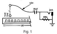
To install the hex fuzz output,
take off the bottom plate (12 screws). Orient the unit top-down, so that
you are facing the rear panel. This jack connects to two ribbon connectors,
which plug into matching sockets (B4 and B5) soldered to the circuit board.
Fig. 1 shows a detail of the left side of B5. Note the designation "6 SG"
just above the left side of the connector, "3 SG" to the right of that,
and a solder connection to the right of "3 SG." A jumper wire goes from
this solder connection to another solder connection directly above it.
Both of these carry the isolated hex fuzz signal.
Decision time: It you dont
want to drill any holes in the GR-300, you will have to give up one of
the jack functions on the back panel so that this jack can carry the hex
fuzz out. I recommend giving up either the string select or sweep on/off
jack. Both of these have three terminals; the ground terminal busses to
the other jacks via bare wire, one terminal is unsoldered, and the remaining
"hot" terminal (the one closest to the circuit board) has a colored wire
going to it. Disconnect this soldered wire and tape up the end, so it wont
short to anything. Connect the "-" end of a 10 micro farad electrolytic
capacitor and one end of a 100K resistor to the hot terminal. Connect the
other end of the resistor to the ground terminal, and the remaining end
of the capacitor to a wire whose free end solders to either of the jumper
solder pads shown in Fig. 1. You now have an individual hex fuzz output.
Vibrato pedal
I dont like the GR-300s
vibrato touch plates, so I disabled them and added a foot pedal option
where pushing down on the pedal increases the vibrato depth. The pedal
must be a control voltage pedal,as described in my article in the
February 1982 issue of Keyboard magazine (page 24). Otherwise, use a standard
volume pedal, connect a 9V battery connector to a 1/4" phone plug (red
wire to hot, black wire to ground), and insert the plug into the pedals
instrument input. As you push down, the pedal output will go from 0 to
9 volts.
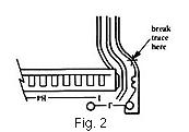
As with the last mod, you
will have to give up another jacks function; I recommend the VCF pedal
jacks hot terminal (the closest to the circuit board), and resolder this
wire to the ground terminal. Now, referring to Fig. 2 (which details the
right side of B4), use an X-acto knife to break the circuit board trace
where indicated. Next, follow along the right-hand side of the circuit
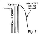
board. As you move towards the foot switches, you will see the legend for
resistor R179 about two-thirds of the way up the board and about an inch
from the side. Move towards the foot switches from this point, and youll
find a jumper wire (see Fig. 3). Solder a wire to the right of this jumper,
and connect the other of this wire to the hot terminal of the VCF pedal
jack.
Check your wiring over carefully,
make sure you didnt short out any adjacent traces (important!), and reassemble
the unit. Plug a control voltage pedal output into the VCF pedals input
to verify that the pedal vibrato function works, and also check that theres
a signal present at the new hex fuzz output jack. If all is well, play
away!
These mods may be simple,
but theyve really perked up the sound of my axe. I hope you like them;
give them a try and let me know what you think.